Build It With Three Shapes
Construct a fully functional everyday object by combining, aligning, or subtracting no more than three primary CAD primitives.
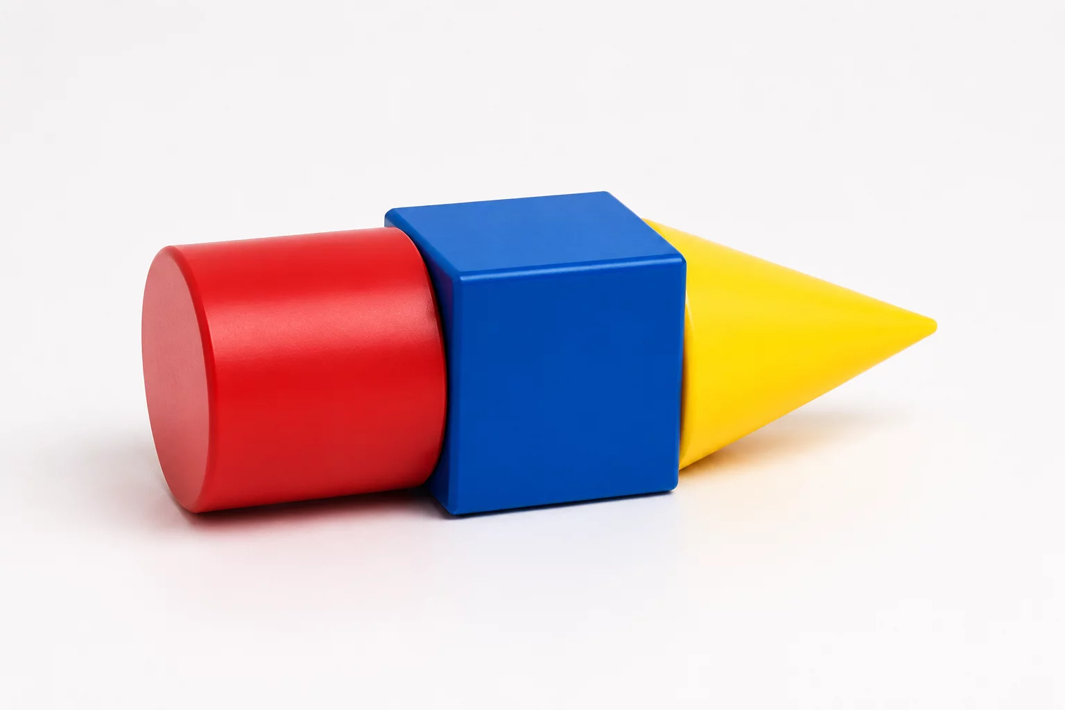
Mandatory Constraints Protocol
Designers frequently overcomplicate CAD assemblies by stacking dozens of tiny decorative parts. Restricting the entire model to exactly three geometric primitives forces creators to focus on boolean cutouts, proportional scaling, and multifunctional surfaces.
Strict Primitive Limit
Use exactly three base solid or hole primitives (such as one box, one cylinder, and one wedge). Every compound element created before final grouping counts against the three-shape budget.
Functional Standalone Utility
The resulting component must fulfill an everyday task—such as organizing cables, supporting an index card, or hooking onto a desk edge—without adhesives or external fasteners.
Support-Free Printability
Preserve at least one flat contact face and keep cantilevered angles below 45 degrees so the object slices cleanly without throwaway support structures.
Engineering Evaluation Matrix
In introductory CAD workshops, learners tend to generate separate solid shapes for every minute feature. The Three Shapes constraint confronts this habit directly by prioritizing geometric economy. When negative hole primitives are treated with equal importance as positive solids, a single subtraction cylinder can create both an internal storage pocket and an external cable passage.
During physical testing, inspect all join points for structural continuity. Primitives must overlap by at least 1.2 mm inside the digital workspace to prevent non-manifold zero-thickness mesh errors during slicing. This disciplined method trains students to approach complex industrial problems with clean, minimal volumetric building blocks.
Acceptance Criteria
- The entire design contains exactly three primitives across both positive solids and negative holes.
- The export produces a single watertight manifold STL mesh with no disconnected floating islands.
- The printed part securely holds its intended load without seam separation along primitive joints.
Software Guide
Tinkercad Workflow
Drag your three primary shapes onto the workplane. Use the Align tool to ensure coaxial alignment before converting secondary bodies into holes. Group all three items into a single solid mesh.
TIP // Align shapes using the workplane tool to ensure zero floating geometry.
Fusion 360 Constraints
Create three distinct base sketches or solid primitives. Apply Boolean Combine operations with Join or Cut actions, keeping the history timeline strictly within three procedural operations.
PARAM // Define User Parameters before extruding primary bodies.
Hands-on Iteration
Slice with a 0.20 mm layer height and 20% grid infill. Verify layer fusion at intersection boundaries to eliminate delamination along the junction seams.
FAB // Verify draft angles and base adhesion before slicing.
Dimensional Boundaries
| Parameter | Constraint Value |
|---|---|
| Max X-Y Footprint | 75 x 75 x 90 mm |
| Min Wall Thickness | ≥ 2.4 mm |
| Interface Clearance | 0.45 mm offset |
| Primitive Count Cap | Exactly 3 Shapes |
Adopt This Card for Your STEM Group
Order printable constraint challenge decks or request tailored CAD classroom curriculum packages.
Inquire Now: 8478786705Leave a Comment
Share your classroom result, design insight, or improvement idea.
Educator & Maker Notes
Peer discussions and classroom constraint iteration results.
Dr. Elena Rostova
STEM Educator 08/18/2026The parametric constraint prompts revolutionized our university robotics lab. Limiting students to 3 distinct CAD primitives forces actual geometric reasoning instead of brute-force modeling.
PARAMETER CHECK: [Wall Thickness >= 2.4mm] // Status: PASSEDClassroom Moderation Active
All STEM challenge submissions and instructor feedbacks are reviewed to ensure instructional accuracy.