Track Overview & Pedagogical Value
In digital fabrication and CAD education, real breakthroughs happen between revision one and revision four. Beginners often treat 3D modeling as a single-attempt task, either accepting clumsy initial drafts or completely discarding a project when a tolerance fails. The Iteration Challenges track counteracts this habit by enforcing disciplined, incremental model evolution. Designers keep their initial design baseline while systematically testing targeted parameter adjustments to reach tighter fits, shorter print durations, and lighter physical weight.
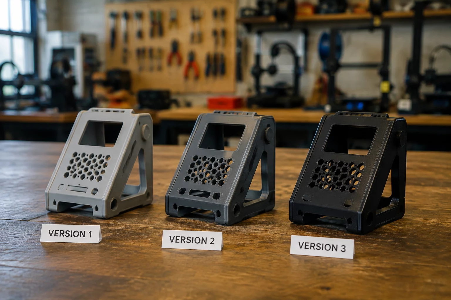
By comparing physical builds side by side across chronological versions (v1, v2, v3), learners observe the tangible connection between digital parameters and physical performance. This practice transforms open-ended software tinkering into authentic engineering cycles where material efficiency, structural stiffness, and print stability take center stage.
Engineering Challenge Boundary
Every subsequent revision must isolate and modify exactly one structural or dimensional variable from the prior build. Altering multiple features simultaneously obscures causal relationships and undermines the analytical rigor of iterative prototyping.
Enforced Constraint Specifications
When advancing from baseline to revision two, modify only one geometric attribute (such as wall thickness, fillet radius, or slot clearance) while keeping all remaining boundaries unchanged.
Optimize the interior structure or outer geometry to reduce total filament volume by a minimum of twenty percent while matching the baseline part's load-bearing ability.
Redesign overhangs and bridge angles to self-support under forty-five degrees, completely eliminating disposable support material during slicing and manufacturing.
Classroom & Makerspace Implementation
Makerspaces and STEM workshops achieve the greatest learning outcomes when physical prototypes are organized in a visible progression along the workbench. Use these sequential steps to foster evidence-driven critique and focused design choices:
- Fabricate Version 1 using rapid draft slicing settings, then inspect and mark structural weak points or clearance issues with a fine-tip pen.
- Duplicate the workspace in Tinkercad or Fusion, apply only the single required adjustment rule, and export Version 2.
- Weigh both parts on a digital scale and run side-by-side fit tests to record measurable improvements in strength and material usage.