Fit Inside a 60 mm Cube
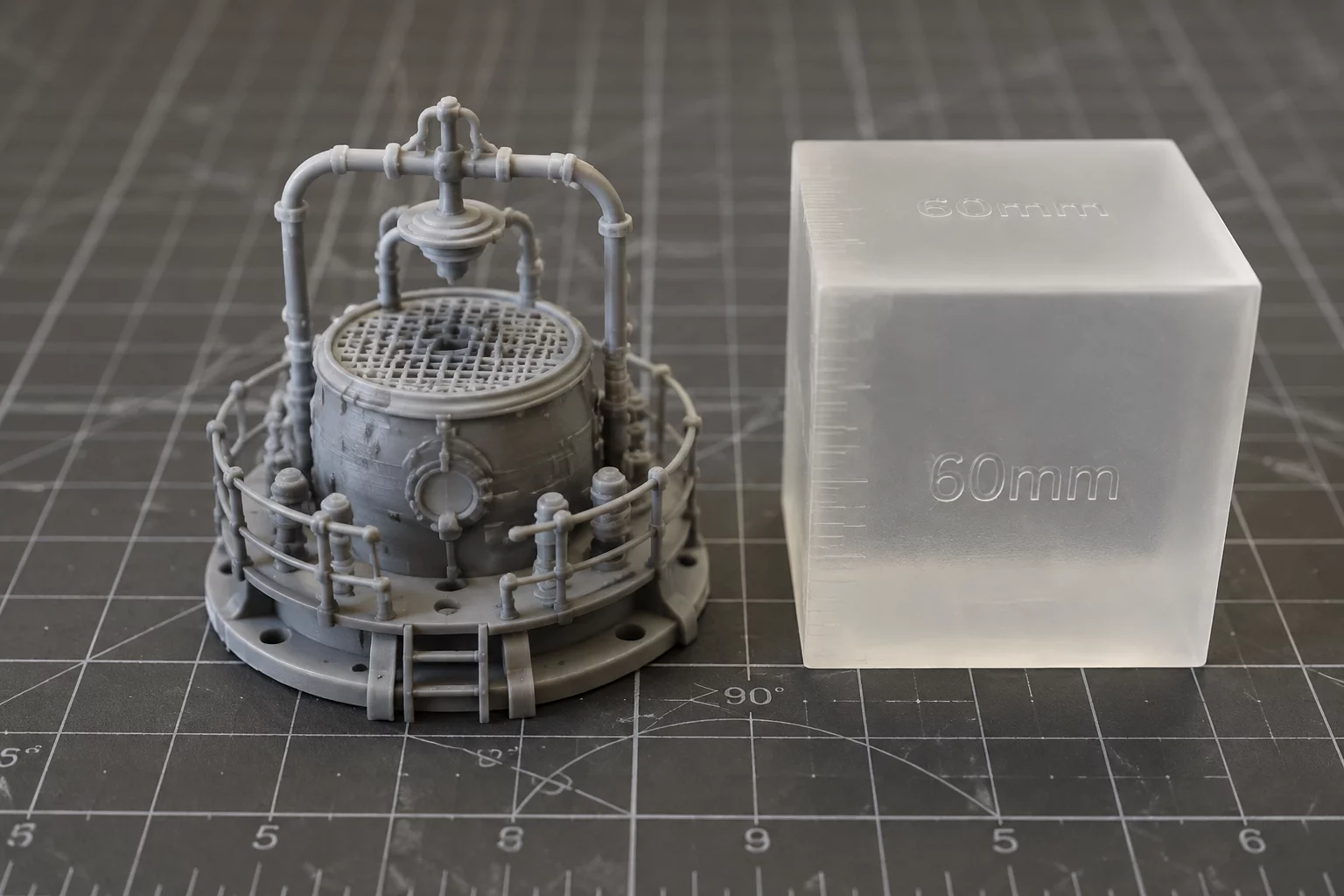
The entire design must fit within a 60x60x60 mm bounding box. Develop spatial economy, eliminate excess mass, and master volumetric limits in CAD.
Mandatory Constraints Protocol
Spatial limitations force designers to prioritize essential features over decorative excess. Every vertex, fillet, and extrusion must remain within the 60.0 mm dimensional envelope across all three primary axes while maintaining functional strength.
Strict 60 mm Bounding Box
No geometry, clip, hinge, or overhang may exceed 60.0 mm in length, width, or height in its default resting configuration.
Structural Wall Stability
Maintain a minimum perimeter wall thickness of 1.6 mm to prevent warping, delamination, and structural failure during rapid 3D printing.
Purposeful Functional Utility
The object must fulfill a tangible task, such as cord management, desktop tool storage, or interlocking modular stacking, within the allocated envelope.
Engineering Evaluation Matrix
Compact envelope constraints challenge students to eliminate dead volume in solid bodies. By designing within a 60 mm cubic boundary, internal cavities and nested geometries must be hollowed or chamfered efficiently. This size fits standard classroom 3D printer batch schedules, allowing fabrication times under forty minutes per student piece.
Checking student prototypes against a physical inspection gage reveals real-world manufacturing variables, including thermal plastic shrinkage and base layer expansion. Designers learn to orient models to place critical mechanical loads parallel to print layer lines.
Acceptance Criteria
- Digital CAD verification confirms total X, Y, and Z dimensions measure ≤ 60.0 mm.
- Fabricated piece slides freely into a physical 60 mm calibration cube without binding.
- Total print time remains under 45 minutes on standard 0.2 mm layer height settings.
Software Guide
Tinkercad Workflow
Place a transparent 60x60x60 mm box on the grid as an inspection envelope. Assemble your model entirely inside this visual bounding box and remove the reference shape before exporting your STL.
TIP // Align shapes using the workplane tool to ensure zero floating geometry.
Fusion 360 Constraints
Create user parameters with MaxBoundary = 60 mm. Construct a construction box sketch with driving dimensions to restrict all sketches and extrusions within bounds.
PARAM // Define User Parameters before extruding primary bodies.
Hands-on Iteration
Print at 15–20% gyroid infill. Check printed parts against a precision caliper or cardboard test fixture to evaluate thermal shrinkage across thin corners.
FAB // Verify draft angles and base adhesion before slicing.
Dimensional Boundaries
| Parameter | Constraint Value |
|---|---|
| Max X-Y Footprint | 60.0 x 60.0 mm |
| Min Wall Thickness | 1.6 mm |
| Interface Clearance | 0.4 mm |
| Primitive Count Cap | 6 Primitives Max |
Adopt This Card for Your STEM Group
Order printable constraint challenge decks or request tailored CAD classroom curriculum packages.
Inquire Now: 8478786705Leave a Comment
Share your classroom result, design insight, or improvement idea.
Educator & Maker Notes
Peer discussions and classroom constraint iteration results.
No notes yet. Be the first educator or maker to submit feedback on this card.
Classroom Moderation Active
All STEM challenge submissions and instructor feedbacks are reviewed to ensure instructional accuracy.