Why Starting with Geometric Primitives Builds Better CAD Habits
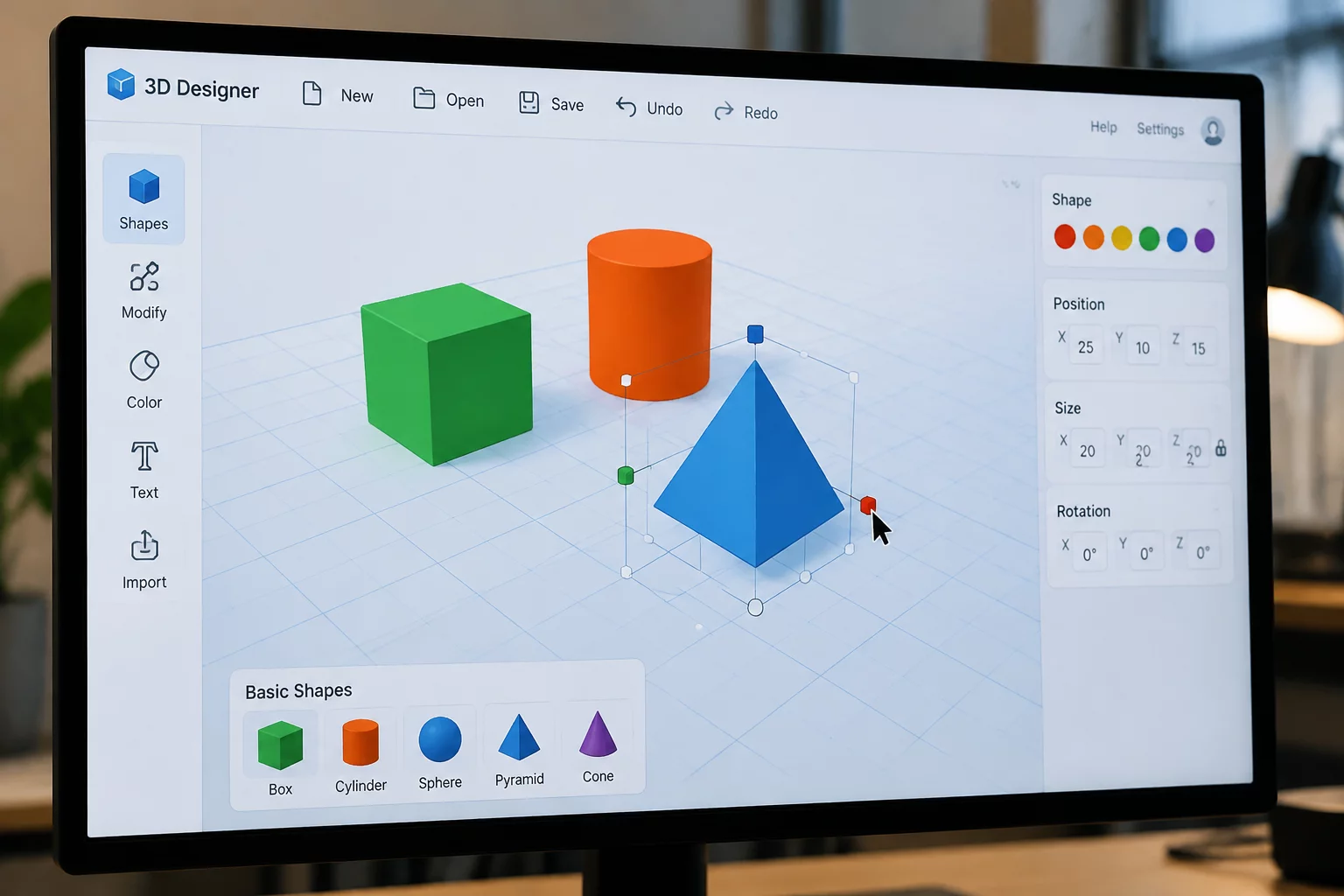
Tinkercad looks deceptively simple at first glance. The browser-based interface places a clean workplane and a tray of geometric primitives right before you. Beginners often attempt complex freehand shapes immediately, only to struggle with messy topology, non-manifold geometries, and failed prints later. When you restrict yourself to basic solids like boxes, cylinders, and wedges, you learn how to decompose complex real-world objects into fundamental geometric components.
This foundational mindset forms the core of parametric engineering. Every intricate industrial component originates from basic boolean operations: unions, subtractions, and intersections. Starting with disciplined constraint exercises accelerates your spatial reasoning faster than wandering through advanced sculpting toolsets without direction.
Great 3D designers do not start by drawing complex curves. They see the underlying primitives hiding inside every functional object.— Mike Torres, Lead CAD Educator
Essential Workspace Mechanics Every Beginner Must Master
Before attempting multi-part assemblies or moving joints, spend time mastering these core digital manipulation mechanics on your Tinkercad workplane:
- Workplane Snap and Grid Precision: Keep your grid set to 1.0 mm or 0.5 mm to ensure clean alignments rather than floating fractions that disrupt 3D printing.
- Hole and Group Workflows: Practice turning solid primitives into transparent hole cutters to hollow out pen cups, notch mounting clips, and bevel sharp edges.
- The Ruler and Dimension Tool: Drop the ruler directly onto your primary reference point to control exact offsets and wall thicknesses numerically rather than eyeballing scale.
- Align and Mirror Utilities: Use the alignment matrix (key L) to center cylinders on rectangular bases with zero manual guessing.
Mastering these four mechanics turns chaotic clicking into predictable mechanical prototyping. You spend less time correcting misalignments and more time refining functional dimensions.
Step-by-Step: Your First Constraint-Driven Tinkercad Project
To put these concepts into practice immediately, tackle our signature beginner challenge: create a custom desk cable clip using exactly three geometric shapes under strict dimensional boundaries.
- Establish the Bounding Envelope: Drag a solid box to the center and size it strictly to 30 mm x 20 mm x 15 mm. This forms the outer protective shell.
- Cut the Cable Channel: Place a cylinder, turn it into a hole with a diameter of 6.5 mm (matching standard USB-C braided cables), align it horizontally, and subtract it from the top surface.
- Create the Snap-In Slit and Chamfer: Use a narrow 2.0 mm wide box hole along the top edge to create the flexible entry slit, then group all shapes together to generate a single manifold solid.
Export the finished grouping as an STL file and inspect its base layer in your slicing software. By keeping the bottom completely flat and adhering strictly to your three primitive shapes, the resulting model prints in under thirty minutes with zero support material required.
Discussion & Peer Reviews
No comments yet. Be the first to leave a comment.